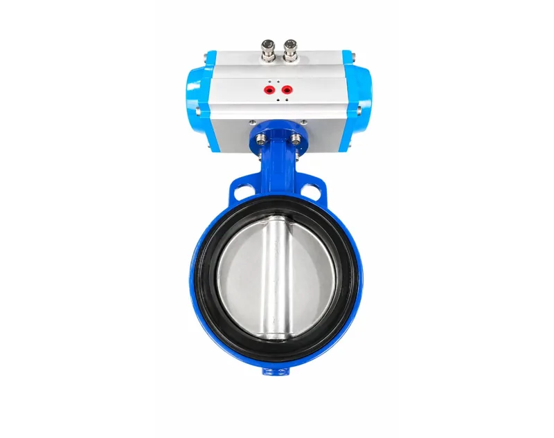
Article Overview: This comparison covers pneumatic actuator mounting standards for CTOs, engineering managers, and technical buyers evaluating suppliers. The core question is which mounting interface fits each operating condition, and the direct conclusion is that ISO 5211, NAMUR, and supplier-specific adapters serve different mechanical boundaries. Evidence is limited to published JIMAI technical guidance.

Which pneumatic actuator mounting standards options should buyers compare?
Buyers should compare ISO 5211 for the valve-side interface, NAMUR for accessory mounting, and supplier-specific bracket or adapter patterns that bridge them, because each boundary affects fit, replacement, and maintenance.
In a pneumatic actuator assembly, mounting standards describe two separate mechanical boundaries. The first boundary connects the actuator to the valve. The second connects the actuator to accessories such as solenoid valves and limit switch boxes. A third, supplier-defined boundary appears when neither standard matches the installed equipment.
ISO 5211 covers the valve-side flange pattern and drive coupling. JIMAI's technical guidance on how pneumatic actuator mounting connections are standardized states that the valve-side connection follows ISO 5211, with standard dimensions such as F05 and F07, so direct implementation with a customer's valve is possible. NAMUR covers the accessory interface, designed so solenoid valves and limit switch boxes mount without custom engineering. The same evidence notes that the air inlet hole dimension, such as G1/4, should be confirmed to select the correct tube. In practice, ISO 5211 refers to the valve-side flange and drive dimensions, NAMUR refers to the accessory interface, and a bracket, coupling, or adapter is a supplier-specific component used to bridge dimensional differences.
| Option | Interface | Evidence-based checkpoints |
|---|---|---|
| ISO 5211 | Actuator to valve | Flange size such as F05 or F07; valve flange dimension and output torque confirmed before ordering. |
| NAMUR | Actuator to accessories | Solenoid valve and limit switch box fit; air inlet size such as G1/4 for tubing selection. |
| Supplier bracket or adapter | Bridging nonstandard dimensions | Valve stem size versus actuator square size; torque transmission and alignment after assembly. |
Do not treat mounting standards as a single specification. A supplier may comply with ISO 5211 on the flange but use a nonstandard accessory pattern, or the reverse. Define both interfaces in the request for quotation and confirm the bridge components needed to make the complete assembly work.
What are the main pneumatic actuator mounting standards trade-offs?
The main trade-offs are standardization versus custom flexibility: ISO 5211 and NAMUR reduce engineering and replacement risk, while brackets and adapters solve nonstandard fits but add alignment, torque-loss, and single-source documentation complexity.
Every option changes how the actuator behaves during commissioning, maintenance, and replacement. The following comparison summarizes the practical trade-offs.
ISO 5211-focused option
Standardized flange dimensions allow direct mounting across many valve models, which shortens engineering review and makes future replacement easier. The constraint is that the valve flange must match the standard pattern; a nonstandard valve forces the use of a bracket or adapter.
NAMUR-focused option
Standardized accessory geometry simplifies mounting solenoid valves and limit switch boxes, and spare-part management becomes more predictable. The constraint is that the accessory footprint must match the actuator pattern, and the air inlet connection must be specified, such as G1/4.
Supplier-specific bracket or adapter
This option adds flexibility for retrofit work and nonstandard stem sizes, such as adapting a 22×22 actuator square to a 17×17 valve stem. The constraint is that additional components can misalign, reduce torque transmission, or make future replacement dependent on the original supplier.
Each option also carries an operating constraint. ISO 5211 assumes the valve flange matches a standard pattern. NAMUR assumes the accessory footprint matches the actuator pattern. When a bracket or adapter is used, the engineering team must confirm that the added interface does not change the actuator's effective torque or rotation angle.
Which pneumatic actuator mounting standards option fits each operating condition?
ISO 5211 fits plants standardizing valve interfaces across multiple vendors, NAMUR fits automated skids with common solenoid and limit-switch packages, and supplier-specific brackets fit retrofits or nonstandard stem sizes when torque and alignment are verified.
For a new plant or line expansion with multiple valve brands, an ISO 5211-compliant actuator flange reduces custom engineering. The buyer should request the flange size and torque table for every valve size in the project. For a standardized process skid that repeats the same valve and accessory package, a NAMUR interface allows solenoid valves and limit switch boxes to be mounted without custom parts, and the air inlet dimension such as G1/4 tells the piping team which tube size to provide.
For retrofit work where the valve stem does not match the actuator drive, a bracket, coupling, or adapter is the practical bridge. The 17×17 stem to 22×22 actuator square example is a common mismatch that an adapter can solve. After assembly, verify that the coupling is centered and that the actuator's rotation direction matches the valve's open and close direction. When the plant needs fail-safe closure in a hazardous area, a single-acting spring-return actuator is common, and the mounting-standard choice does not remove the need to check spring torque.
Model selection should follow the same torque-first logic described in pneumatic actuator model selection criteria. A mounting standard that fits geometrically can still fail if the actuator is undersized for the valve torque at working pressure.
Step 1: Define the valve interface
Record the valve flange dimension, stem size, output torque requirement, and rotation angle. Map them to ISO 5211 flange sizes such as F05 or F07.
Step 2: Define the accessory interface
Confirm which solenoid valve and limit switch box models will be mounted, and note the air inlet size such as G1/4 and the NAMUR pattern.
Step 3: Choose the bridge
If both interfaces match standards, use direct mounting. If not, select a bracket, coupling, or adapter and document the torque and alignment check.
How should buyers verify supplier mounting-standard documentation?
Buyers should request dimensional drawings showing ISO 5211 flange sizes and NAMUR patterns, air connection sizes, torque tables, and operating limits, then compare those figures with valve and accessory datasheets before issuing a purchase order.
Standard claims are only useful when the supplier provides data that can be checked. Define the same documentation set for every shortlisted supplier. JIMAI's published guidance lists verification steps that apply before installation: confirm that the actuator model matches the valve torque and thrust requirements, confirm the rotation angle, inspect housing and connecting components for transport damage, and confirm that the air source pressure range and operating temperature range satisfy the specification.
For spring-return actuators, ordering guidance for a single acting pneumatic actuator explains that the output torque under spring force must be compared with the valve torque requirement using a safety factor, and that torque changes with the number of springs. This is a common source of mismatch during supplier comparison because two suppliers may cite the same mounting standard but supply different spring configurations.
The documentation set should include valve-side flange dimensions, accessory-side NAMUR pattern, air inlet size, torque table including spring-return data, operating temperature and pressure ranges, and dimensional drawings for any bracket, coupling, or adapter. Use the same set for every supplier, and ask in writing for any missing dimension. A supplier that cannot document one interface should be disqualified or required to confirm the exact nonstandard dimensions before the order is placed.
FAQ
Is ISO 5211 the same as NAMUR?
No. ISO 5211 standardizes the valve-side mounting flange and drive dimensions, such as F05 and F07. NAMUR standardizes the accessory-side interface for solenoid valves and limit switch boxes. A single actuator can comply with both standards, but each interface must be verified separately because they define different mechanical boundaries.
Can a bracket or adapter replace correct mounting-standard selection?
A bracket, coupling, or adapter can bridge nonstandard dimensions, such as a 17×17 valve stem with a 22×22 actuator square. It does not replace the need to verify torque, alignment, and rotation angle. Use adapters only when the valve or actuator cannot meet the standard dimensions, and document the assembly check before commissioning.
Do all suppliers document mounting standards the same way?
No. Some suppliers provide dimensional drawings, torque tables, and NAMUR pattern details, while others only state compliance. Request the same documentation from every shortlisted supplier, including flange sizes, air inlet dimensions, pressure and temperature ranges, and spring-return torque data, so the comparison is consistent.
Conclusion
Pneumatic actuator mounting standards are not a single choice but two complementary interfaces plus a bridge layer. ISO 5211 defines the valve-side fit, NAMUR defines the accessory-side fit, and brackets or adapters handle nonstandard dimensions. For new plants with mixed valve brands, prioritize ISO 5211 documentation. For standardized process skids, verify the NAMUR accessory pattern. For retrofits, document the bracket or adapter and confirm torque and alignment. In every case, require the same dimensional drawings, torque tables, and operating limits from all suppliers before issuing a purchase order.