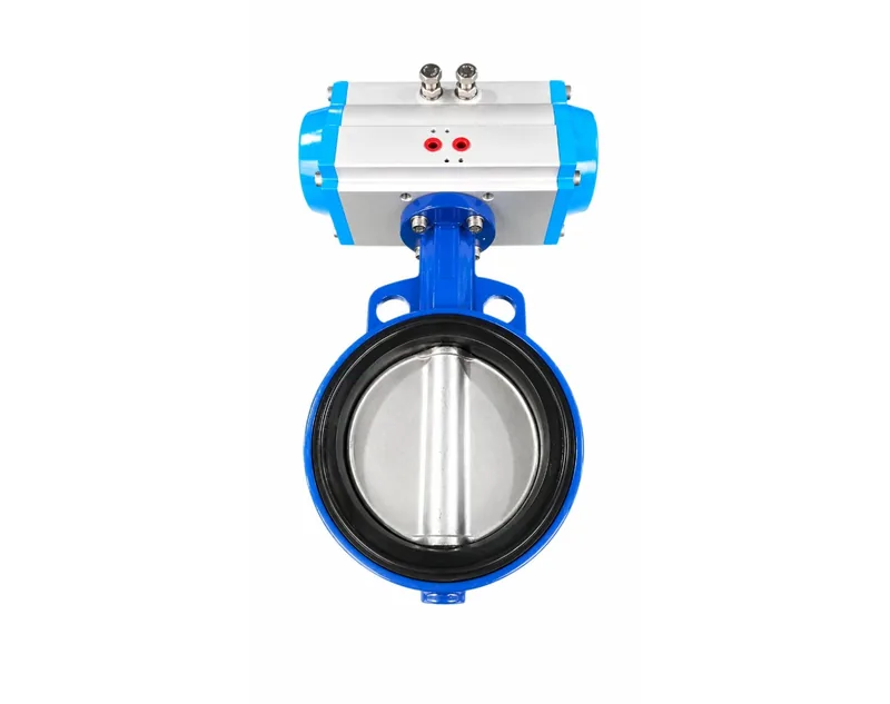
Article Overview: This article explains pneumatic actuator solenoid valve wiring for maintenance teams, system integrators, and technical buyers. It covers NAMUR port alignment, direct versus remote mounting, coil wiring, and first-line fault checks. Conclusions are based on the manufacturer's installation and accessory documentation; actuator torque sizing is not included.
How do I connect a solenoid valve to a pneumatic actuator?
Connect the solenoid valve by aligning its NAMUR interface with the actuator port pad, tightening the mounting screws evenly, and connecting the regulated air supply to the inlet and pilot ports before testing operation.
In a complete valve package, the solenoid valve is the directional-control element between the compressed air supply and the actuator. The coil shifts an internal pilot when energized, and the shifted pilot sends air to the correct actuator port. Manufacturer accessory guidance describes common configurations such as 3/2-way, 5/2-way, and 5/3-way solenoid valves; the first digit refers to the number of ports and the second to the number of switching positions.
The actuator side of the connection commonly follows the NAMUR accessory standard, allowing a solenoid valve to be mounted directly on the actuator port pad without a custom bracket. Air inlet dimensions such as G1/4 are also published so that you can match the fitting and tubing to the actuator. Because the solenoid valve is normally installed with a filter-regulator and limit switch box or similar devices, review common pneumatic actuator accessories before finalizing a package layout.
Step 1: Verify actuator rotation and valve position
Confirm that the actuator output rotation corresponds with the valve's open and close direction. Align the actuator with the valve stem and tighten the mounting bolts evenly to avoid binding.
Step 2: Position the solenoid valve on the NAMUR pad
Clean the port pad, place the solenoid valve so its ports align with the actuator pilot ports, and tighten the mounting screws in a balanced sequence so the gasket is not pinched.
Step 3: Connect the regulated air supply
Connect a filtered air supply to the solenoid inlet. The manufacturer's ball-valve installation guidance recommends setting pressure to 0.4 to 0.6 MPa after the filter-regulator; use the actuator nameplate as the final authority for the specific package.
Step 4: Shift manually before applying coil power
Use the manual override or switch the gas line by hand and confirm that the actuator moves smoothly to both end positions. Only after this test should you wire the coil.
For complete installation of a pneumatic ball valve, follow the pneumatic ball valve installation guide after the actuator and solenoid are connected; that guide contains the same orientation, pressure, and testing steps in a valve-specific sequence.
Should the solenoid valve be mounted directly on the actuator or installed remotely?
Mount directly when response speed, compactness, and fewer tube connections are the priority; mount remotely when service access or panel placement matters, then account for longer pilot lines and slightly slower response.
Direct mounting on a NAMUR pad removes a set of interconnecting tubes between the solenoid and the actuator, so the pilot signal does not have to travel through fittings before entering the cylinder. That tends to make the actuator respond quickly and makes the assembly compact. The trade-off is that the solenoid shares the actuator's location, which may not be convenient for maintenance and may expose the coil to the actuator's ambient heat or vibration.
Remote mounting is useful when the solenoid must be placed inside a control cabinet, away from fluid spills, or where an operator needs easy access. Remote mounting should not be treated as a lower-cost shortcut. Air lines add volume, and every fitting is a potential leak point. Use the same or larger tubing than the actuator port size and keep the lines as short as the layout allows. If remote mounting is used on a spring-return actuator, be sure the exhaust path remains free so the spring can return the valve reliably.
Direct interface mounting
Short pilot passages, fewer fittings, simpler compact assembly when the actuator has a NAMUR interface. The solenoid valve must be compatible with the pad and may need to be removed to service the actuator.
Remote tubing installation
More freedom in placing controls and better access for maintenance. Longer pilot paths can slow response, and additional connections add leak points that should be checked with a pressure or bubble test.
At the plant level, solenoid placement is only one part of a larger control design. A guide to optimizing valve control systems with pneumatic actuators helps engineering teams match spring-return fail-safe and double-acting configurations to the chosen mounting layout.
How do I wire a solenoid valve coil to a control signal?
Wire the coil to a de-energized control circuit that matches the nameplate voltage, connect the supply and return conductors to the coil terminals or plug connector, then power the circuit and confirm the air direction changes.
The electrical side of the installation is straightforward, but it must be done with the pneumatic side already verified. A solenoid coil has two electrical terminals in most configurations. Some actuators use a terminal block, and others use a plug connector. The exact connection method is less important than confirming that the control voltage matches the coil rating. Manufacturer installation examples refer to a 24V supply, but the actual valve can be rated for other DC or AC values; always check the coil nameplate.
This article intentionally stops at the field wiring level. A PLC or DCS may supply the digital output that switches the solenoid, but program logic, interlock design, and network configuration are outside the scope.
Step 1: Confirm the coil voltage and supply type
Read the solenoid nameplate and verify that the control circuit is the same voltage and frequency or DC polarity class. Do not rely on the plant's general supply voltage.
Step 2: De-energize the circuit
Lock out and verify zero energy before touching the terminals. Confirm that no secondary feed can energize the coil while you are wiring.
Step 3: Land the conductors on the coil terminals
Connect the supply conductor and the return or common conductor in the order shown on the solenoid. Use the connector supplied with the valve and provide strain relief for the cable.
Step 4: Apply power and observe the shift
Energize the coil and listen for the click of the pilot valve, then watch the actuator stroke. If the coil does not shift, do not increase voltage; remove power and check wiring and the manual override.
Why is the pneumatic actuator not responding after the solenoid valve is installed?
Check whether the problem is pneumatic or electrical by verifying regulated supply pressure, using the manual override, then measuring coil voltage; if manual override moves the actuator, the fault is likely electrical or pilot-stage wiring.
Start by verifying the prepared air pressure. Manufacturer guidance suggests a filter-regulator adjusted to approximately 0.4 to 0.6 MPa for a pneumatic ball valve package. Pressure must also be within the actuator's nameplate range. If you have a spring-return actuator, confirm that the spring side is not blocked. Then use the manual override to shift the solenoid, which tells you whether the problem is upstream of the coil.
- No audible click and no actuator movement
- Check that supply voltage is present at the coil terminals during the command. Inspect the connector, terminals, and cable continuity, and confirm the coil voltage rating matches the circuit.
- Audible click but no actuator movement
- Check the pilot air supply pressure and make sure the inlet, exhaust, and pilot ports are free of debris or burrs. Confirm the tube between solenoid and actuator is not kinked or reversed.
- Actuator moves to one end only
- For a double-acting actuator, verify that both output ports have air during the corresponding commands. For a single-acting actuator, confirm spring return is not blocked by a plugged exhaust port.
FAQ
What do 3/2-way and 5/2-way mean on a solenoid valve?
The first number counts the working ports, and the second number counts switching positions. A 3/2-way solenoid valve has three ports and two positions, which is commonly used with a single-acting or spring-return cylinder. A 5/2-way valve has five ports and two positions and is typically used when a double-acting cylinder or rack-and-pinion actuator must receive air to both chambers.
Can I test the actuator before wiring the coil?
Yes. If the solenoid valve has a manual override, shift it manually while the air supply is on. The actuator should stroke to its end position, and the valve should move to the expected open or closed position. This verifies the pneumatic portion of the circuit before you invest time in electrical troubleshooting.
What air pressure should be supplied after the solenoid valve is installed?
Use the pressure printed on the actuator nameplate. As a point of reference, the manufacturer's installation documentation for a pneumatic ball valve package recommends setting the filter-regulator to 0.4 to 0.6 MPa. Pressure below the actuator minimum may produce slow or incomplete movement, while excessive pressure can stress components.
Conclusion: Complete the Air Path Before the Electrical Path
Wiring a solenoid valve to a pneumatic actuator is a two-part task. First establish the correct mechanical and pneumatic connection: matched actuator rotation, NAMUR port alignment, regulated and filtered supply pressure, and a manual-override test. Then verify coil voltage and wire the control circuit. Working in that order makes troubleshooting predictable and avoids unnecessary coil or actuator replacements.