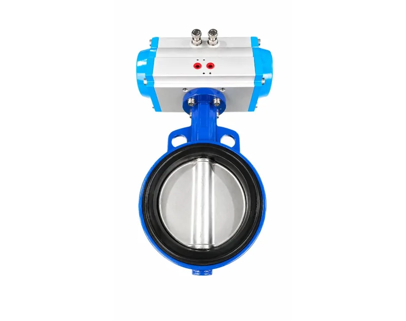
Article Overview: This guide helps procurement managers, sourcing teams, and project engineers translate operating requirements into a pneumatic actuator mounting bracket selection. It answers how to choose a bracket and coupling, what to verify before RFQ, and which trade-offs matter. The conclusions are bounded by published installation and mounting-connection guidance, not by independent laboratory data.
How Should Buyers Approach Pneumatic Actuator Mounting Bracket Selection?
Start with the valve interface and torque demand, then translate those into a bracket, coupling, and adapter. The bracket supports the actuator, the coupling transmits rotation, and the adapter reconciles drive-square and stem sizes.
Mounting bracket selection is not a standalone decision. The bracket attaches the actuator to a valve or machine frame, the coupling connects the actuator drive to the valve stem, and an adapter changes the actuator square size when the stem dimension differs. Each part must be specified from the same operating data set.
If the drive technology is still open, review how to select the right actuator, electric versus pneumatic, before locking bracket dimensions. Once the actuator type is fixed, gather the data below.
- Valve flange pattern and stem size: Confirm the ISO 5211 pattern and the stem shape and dimension. Published guidance cites patterns such as F05 and F07.
- Torque and thrust requirement: Compare valve torque, including fail-safe spring torque for single-acting actuators, with the actuator output.
- Rotation angle: Confirm quarter-turn operation or intermediate positions such as 0-45-90 degrees.
- Accessory mounting: Identify solenoid valve, limit switch, positioner, and manual override positions, because NAMUR accessory mounting affects bracket clearance.
- Environment: Record operating temperature range, washdown, corrosive exposure, and any pipe load that the bracket must absorb.
These five data points form the selection criteria. A bracket is not sized by actuator brand alone; it is sized by the bolt pattern of the valve, the output square of the actuator, and the clearance needed for accessories. When the operating needs change, such as a higher fail-safe torque or a different supply pressure, re-run the same criteria rather than reusing a previous bracket design.
Procurement checkpoint: If the actuator model changes after bracket selection, recheck the bolt pattern, output square, and overall envelope. Do not assume the same bracket works with a different actuator size.
Which Mounting Bracket and Coupling Trade-Offs Matter Most?
Compare standardized interfaces against custom adapters, material compatibility against weight, and alignment precision against installation speed. No single trade-off wins across all applications; the balance depends on the valve, duty cycle, and environment.
The most valuable trade-offs are usually visible within the same application:
Standard interface versus custom adapter
ISO 5211 standardizes the valve-side bolt pattern, while NAMUR standardizes accessory mounting. Standard parts make future replacement easier and reduce engineering review. A custom adapter becomes necessary when the actuator output square and valve stem differ; JIMAI cites the example of a 22 mm by 22 mm actuator output connected to a 17 mm by 17 mm valve stem through an adapter.
Strength and stiffness versus compact envelope
A heavier or stiffer bracket can reduce deflection, but it adds load to the valve body and pipe. A compact bracket improves access in tight installations but gives less predictable torque reaction if alignment is imperfect.
Alignment precision versus installation speed
A precision-machined coupling bore and keyway reduce stem stress and slip but require more careful measurement. Fixed bolt patterns speed assembly but allow less correction when the stem is not concentric with the actuator output.
These trade-offs are not mutually exclusive. In practice, a buyer might choose a standard ISO 5211 bracket for the valve connection and a custom coupling for an unusual stem, as long as the supplier's drawing review confirms both parts before final approval.
Material compatibility is another common trade-off. As a hypothetical example, a coated carbon steel bracket may be acceptable in a dry indoor environment, while a stainless steel bracket may be specified for washdown or corrosive service. Confirm the surface treatment and material grade with the actuator supplier rather than assuming the bracket is compatible with the valve body material.
Actuator model selection changes the torque and envelope data that the bracket must support. Work through how to select the right pneumatic actuator model before finalizing the coupling bore, especially when a spring-return version is under consideration. Published guidance notes that single-acting and double-acting actuators share the same external appearance, so the bracket envelope may stay the same even though torque verification differs.
What Should Buyers Verify Before Ordering Mounting Hardware?
Before ordering, verify the valve flange pattern, stem size and shape, actuator output torque, rotation angle, drive square, and accessory mounting standard. Confirm these against the supplier's drawing review rather than relying only on the model number.
Step 1: Document the valve interface
Provide the valve flange dimension, stem size and shape, and the mounting standard such as ISO 5211. Supplier guidance requires this information before order placement.
Step 2: Confirm actuator torque and rotation
Compare the valve torque requirement with the actuator output, including spring-return torque for fail-safe duty. Confirm the rotation angle, including intermediate positions when required.
Step 3: Map bracket, coupling, and adapter dimensions
Define actuator output square size, valve stem size, coupling bore and keyway, bracket height, bolt spacing, and any adapter needed between different square sizes.
Step 4: Validate accessory and air connections
Check NAMUR accessory mounting, solenoid valve interface, limit switch position, and air inlet port size where this affects bracket clearance.
Step 5: Set acceptance checks
Require dimensional approval, material or surface treatment documentation, and a fit check before production. Put acceptance criteria into the RFQ.
| Verification point | What to confirm | Why it matters |
|---|---|---|
| Valve flange pattern | ISO 5211 pattern such as F05 or F07 | Prevents bolt-hole mismatch on the bracket |
| Valve stem dimensions | Diameter and shape, including square or keyway | Determines coupling bore or adapter size |
| Actuator output torque | Valve torque compared with actuator rating, including spring torque | Prevents undersized actuation and premature failure |
| Rotation angle | Quarter-turn or intermediate position requirement | Ensures bracket and limit switch alignment |
| Accessory interface | NAMUR pattern and air inlet port size | Avoids additional adapters during commissioning |
| Operating conditions | Air pressure range and temperature range; cited guidance includes 4-7 bar and -20°C to 80°C | Aligns material, seal, and coating selection |
RFQ language should ask for the same data from every bidder: valve flange dimension, stem size and shape, actuator output torque, rotation angle, drive square size, coupling bore and keyway, bracket hole pattern, NAMUR accessory pattern, and air inlet port size. If a supplier cannot confirm these dimensions in writing, the offer should be treated as incomplete rather than assumed acceptable.
Shared terminology matters during supplier evaluation. Review how pneumatic actuator mounting connections should be standardized so every bidder responds to the same drawing package and dimensional criteria.
Sourcing risk: If the RFQ omits stem dimensions, flange pattern, and torque, a supplier may propose an interface that needs field machining. Require dimensional approval before production and keep that approval in the procurement record.
Keep the approved dimensional drawing as part of the purchase record. At goods receipt, compare the delivered bracket and coupling against that drawing before installation. This reduces the chance that a mismatch is discovered only after the actuator is bolted to the valve.
FAQ
What is the difference between a mounting bracket and a coupling?
A mounting bracket fastens the actuator to a valve or machine frame and keeps the actuator aligned. A coupling connects the actuator drive to the valve stem so torque transfers reliably. An adapter changes the drive-square size when actuator and stem dimensions differ.
Do buyers need an adapter with every bracket order?
Not always. An adapter is required only when the actuator output square and valve stem size differ, such as a 22 mm actuator square driving a 17 mm stem. Confirm both dimensions in the RFQ so the supplier can include the correct coupling or adapter.
Should bracket material match the valve body material?
Matching material is not mandatory, but the bracket must withstand the same operating temperature range and environmental exposure as the valve and actuator. Confirm material, coating, and any washdown or corrosive-duty requirements before ordering.
What documentation should a buyer request with mounting hardware?
Ask for a dimensioned drawing, material or surface treatment information, and confirmation of the ISO 5211 and NAMUR interfaces. Keep the drawing as the acceptance baseline and verify delivered parts against it before installation.
Conclusion
Bracket and coupling selection starts with the valve interface, torque demand, rotation angle, and environment. Put those parameters in the RFQ, require dimensional approval before production, and use the approval as the acceptance basis. This reduces fit-related delays, simplifies spare parts management, and gives procurement a clear audit trail. Treat the bracket and coupling as engineered components, not generic accessories, and your supplier will have a concrete basis for confirming the fit before shipment.