Article Overview: This comparison examines pneumatic actuator mounting standards, including ISO 5211, NAMUR, and DIN-style patterns, for CTOs, technical architects, and procurement teams. It defines the options, explains the trade-offs, and gives conditional fit guidance. The direct conclusion is to evaluate each interface layer separately, then verify with drawings. Evidence is bounded by supplier installation and connection guidance in the JIMAI knowledge base.
Which pneumatic actuator mounting standards comparison options should buyers compare?
When evaluating pneumatic actuator mounting standards, buyers should compare three interface layers: the ISO 5211 valve-to-actuator pattern, the NAMUR accessory mounting pattern, and DIN-style legacy or regional patterns. Each layer answers a different compatibility question, so evaluate them separately rather than as one standard.
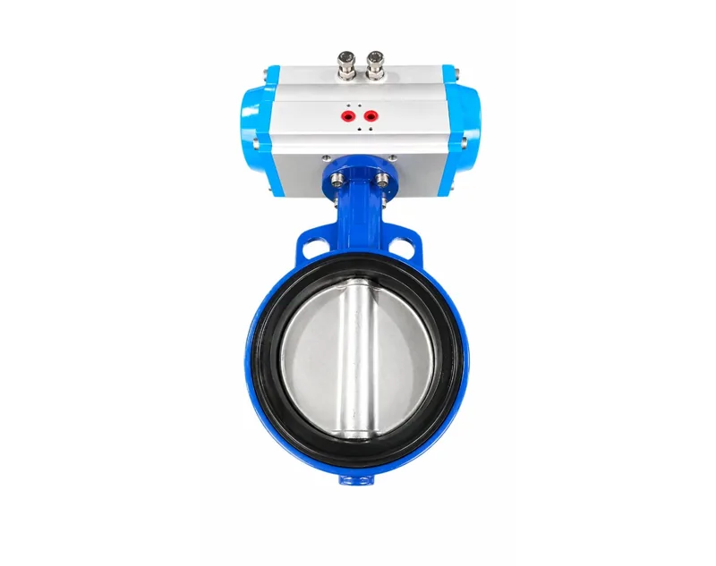
The supplier guidance in the supplied evidence distinguishes two clearly defined interfaces. The valve-side connection follows ISO 5211, with international dimensions such as F05 and F07. This interface determines whether the actuator can bolt directly to a ball valve, butterfly valve, or damper. The accessory-side connection follows NAMUR, and it is designed to mount a solenoid valve and limit switch box. The same guidance also calls out the air inlet dimension, for example G1/4, because it determines which tubing and fittings can be used.
In this comparison, the label DIN-style covers legacy or regional patterns; it is not a single standardized pattern in the supplied evidence. For example, legacy equipment and some regional product lines may be labeled DIN without sharing a single bolt circle or pilot diameter. Treat the DIN label as a hint that a drawing check is required, not as a substitute for ISO 5211 or NAMUR documentation.
Key specification comparison
Use this table to assign each option to the interface it controls. The rows are based on supplier installation guidance and should be confirmed against the component drawing before procurement.
| Criterion | ISO 5211 valve interface | NAMUR accessory interface | DIN-style patterns |
|---|---|---|---|
| Primary connection | Actuator to valve | Actuator to solenoid valve, limit switch box, and similar accessories | Legacy or regional actuator-to-valve or actuator-to-accessory patterns |
| Size examples in evidence | F05, F07 | G1/4 air inlet example | Validate against component drawing |
| Typical use | Direct mounting on quarter-turn valves and dampers | Compact pilot-air and position-feedback mounting | Retrofit and replacement on older installations |
| Compatibility question | Will the actuator bolt pattern match the valve flange? | Will the solenoid or limit switch pattern match the actuator top face? | Does the existing pattern correspond to a documented standard? |
| Primary risk | Misalignment prevents bolting and torque transfer | Mismatch prevents pilot-air or signal connection | Non-standard pattern requires adapters, machining, or custom brackets |
To see how these interface rules are applied in practice, review the guidance on standardized pneumatic actuator mounting connections. It walks through preparation steps such as verifying torque, rotation angle, air pressure range, and the valve flange dimension before ordering.
What are the main pneumatic actuator mounting standards comparison trade-offs?
The main trade-offs are dimensional compatibility, component availability, torque transfer, and maintenance access. ISO 5211 determines valve connection; NAMUR determines accessory connection; DIN-style patterns add legacy compatibility risks. Choose based on the valve flange, actuator output, and solenoid or limit switch mounting needs.
Trade-offs are not about which standard is superior. They are about what each interface controls and how much verification you need before installation. The following blocks compare the decisions by dimension.
Dimensional compatibility
ISO 5211: Defines the valve-side pattern, including example sizes such as F05 and F07. If the valve flange and actuator match, you can bolt directly without an adapter.
NAMUR: Defines the accessory-side pattern. It reduces bracket complexity for solenoid valves and limit switch boxes because the ports and mounting hole positions are standardized for compact devices.
DIN-style: May appear on older or regional actuators, but the term does not guarantee a single pattern. You must compare drawings to determine whether an adapter bracket is needed.
Buyer note: Dimensional mismatch is a frequent cause of field rework. Request the actuator and valve drawings together and compare the bolt circle, pilot, and shaft key before ordering.
Component availability and sourcing
ISO 5211: Because this is an international standard, suppliers can provide direct-mount options when the valve flange uses the same pattern. This reduces the chance of a proprietary-only fit.
NAMUR: The supplied guidance describes NAMUR as designed for easy mounting of solenoid valves and limit switch boxes, so accessory selection is straightforward when the actuator carries the pattern.
DIN-style: Legacy patterns may depend on a single supplier or an older product generation. For example, if the original pattern is not documented, you may need an adapter or full actuator replacement.
Buyer note: For example, in a plant with several generations of equipment, list the interface pattern for each mounting point. This reveals how many adapter types you will need to stock.
Torque transfer and alignment
ISO 5211: The valve-side pattern transmits torque from the actuator drive to the valve stem. A correct match preserves rated output; a loose fit introduces backlash and uneven wear.
NAMUR: The accessory-side pattern does not carry primary torque, but it supports pilot-air and position feedback. Misalignment here can cause signal errors or air leakage at the gasket face.
DIN-style: Consider a retrofit installation as an example: an old drive shape may be combined with a new valve flange. In that case, torque transfer depends on any adapter's tolerances, so verify the keyway and square drive dimensions.
Buyer note: Actuator architecture also affects how torque is delivered. The comparison of heavy duty vs. rack-and-pinion pneumatic actuator designs explains how housing and drive train choices change what you can bolt to the valve.
Which pneumatic actuator mounting standards comparison option fits each operating condition?
No single standard fits every plant. ISO 5211 suits standardized valve automation, NAMUR suits compact accessory mounting on quarter-turn actuators, and DIN-style patterns suit retrofit or regional legacy fleets. Match the interface to the valve, accessory, and maintenance environment before selecting.
Use the following flow to apply the comparison to a specific purchase. It converts the standards comparison into a site-specific decision.
Step 1: Define the operating zone
Record the valve type, required torque, air supply pressure range, and temperature limits. The supplier guidance in the evidence gives a typical air pressure range of 4-7 bar and an operating temperature range of -20°C to 80°C for standard installations. This determines which actuator series is eligible before you evaluate mounting patterns.
Step 2: Identify the valve flange pattern
Measure the valve flange bolt circle, pilot diameter, and stem shape. If the valve follows ISO 5211 sizes such as F05 or F07, you can select an actuator with the matching valve-side pattern. If, for example, the valve uses a DIN-style or proprietary pattern, the decision changes: choose an actuator that matches it, or plan for an adapter and verify torque transfer with it fitted.
Step 3: Select the accessory pattern
Decide which solenoid valve, limit switch box, or position feedback device will be mounted. If they use NAMUR, the actuator top face should provide the NAMUR pattern and the correct air inlet, such as G1/4. This step is separate from the valve-side decision because a single actuator can carry an ISO 5211 bottom pattern and a NAMUR top pattern at the same time.
Step 4: Validate legacy and regional patterns
For retrofit work, consider a hypothetical example where the existing actuator or valve uses a DIN-style pattern that is not fully documented. If the pattern matches a current supplier drawing, replacement is direct. If not, treat this as a non-standard interface that needs an adapter or machining before the project proceeds.
Conditional fit guidance can be summarized as follows. Choose ISO 5211 as the primary valve-side interface for new standardized plants because it supports direct bolt-on valve options. Choose NAMUR for the accessory-side interface whenever the process control loop will use solenoid valves and limit switch boxes. Choose DIN-style patterns only when the existing installed base already uses them and the risk of adapters or custom machining is acceptable.
For dusty or corrosive environments, the mounting pattern matters less than the seal and material grade, but the interface still affects maintenance time because you must disassemble the same bolted joint repeatedly. A documented standard makes replacement predictable; an undocumented DIN-style pattern makes it a field engineering exercise.
The interaction between mount pattern and fail-safe behavior matters especially on spring return units. If the actuator uses a spring return module, the available torque changes with spring count, and the same pattern must still transmit that torque reliably at end-of-stroke. The double acting vs. spring return pneumatic actuator comparison explains how those variants differ in torque output and fail-safe positioning, which affects the torque envelope you should use when sizing the valve-side pattern.
FAQ
Is DIN the same as ISO 5211?
No. ISO 5211 defines the valve-to-actuator mounting interface with dimensions such as F05 and F07, while NAMUR defines the accessory interface. DIN-style is a looser category for legacy or regional patterns. Always compare dimensional drawings rather than assuming equivalence.
Can an ISO 5211 actuator mount a NAMUR solenoid valve directly?
Not automatically. The ISO 5211 pattern controls the actuator-to-valve connection, while the NAMUR pattern controls the solenoid or limit switch interface. Some actuators provide both patterns, but you must verify the bolt circles and port locations on the same actuator before ordering.
Should I standardize on ISO 5211 for all new plants?
For new plants, ISO 5211 on the valve side and NAMUR for accessories is a practical combination and simplifies sourcing. However, for example, if your existing fleet uses DIN-style patterns, you may need adapters, machining, or duplicate inventory. Confirm the installed base and accessory set before standardizing.
Conclusion: Evaluate Each Interface, Then Verify
Pneumatic actuator mounting standards should be treated as three interface decisions, not one global standard. ISO 5211 defines the valve-side pattern, NAMUR defines the accessory-side pattern, and DIN-style patterns represent legacy or regional variants that require drawing-level verification.
The right choice depends on the valve flange, the accessory set, the age of the installed base, and the torque envelope of the actuator. For new automated plants, an ISO 5211 valve interface with a NAMUR accessory interface is a practical default because both are documented in the supplier guidance.
Before ordering, confirm the bolt circle, pilot diameter, drive shape, air inlet, and port positions against the component drawings. This validation step will prevent common field mismatches and keep the mounting decision from becoming a maintenance problem.