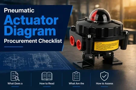
Article Overview: This guide provides procurement decision-makers with a structured approach to interpreting and evaluating pneumatic actuator diagram drawings. It covers essential drawing elements, supplier assessment criteria, risk mitigation strategies, and actionable next steps. Whether you are sourcing for a new project or replacing existing equipment, understanding the pneumatic actuator diagram is critical to ensuring technical fit, cost efficiency, and reliable operation.
What Does a Pneumatic Actuator Diagram Include?
A pneumatic actuator diagram is the technical blueprint that outlines the actuator's internal components, pneumatic connections, control signals, and mounting interfaces. For buyers, reading this diagram correctly prevents mismatched specifications and costly rework. Key elements typically include:
- Actuator type (rack-and-pinion, scotch-yoke, or linear)
- Port sizes and positions (air inlet/outlet)
- Spring-return fail-safe configuration (spring-to-open or spring-to-close)
- Mounting dimensions and shaft connection details
- Control accessories (solenoid valve, limit switch box, positioner)
Each detail directly impacts procurement decisions: port size affects tubing and fitting costs; fail-safe orientation determines emergency shutdown behavior; mounting dimensions must match the valve or gearbox. Without a clear diagram, even a technically correct actuator may fail to integrate.
How to Read a Pneumatic Actuator Diagram for Procurement
When you receive a pneumatic actuator diagram from a supplier, follow this structured approach to extract actionable information. Use these steps to compare multiple offers side by side.
Step 1: Identify the Actuator Type and Operating Principle
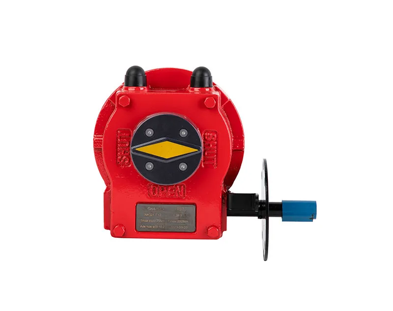
Locate the actuator classification label—rack-and-pinion actuators are compact and widely used for quarter-turn valves; scotch-yoke actuators produce higher torque at end-of-travel; linear actuators suit gate valves. The diagram should show the internal mechanism. If the drawing lacks a cross-section or description, request clarification.
Step 2: Verify Port Positions and Air Connections
Check the air inlet port (usually marked “1” or “P1”) and outlet (“2” or “P2”). Confirm that the orientation matches your piping layout. Also review the exhaust port location—some diagrams include muffler specifications. Mismatched porting can require additional adapters, adding cost and leak points.
Continue reviewing the torque output table (often on the same drawing) to ensure the actuator can overcome valve torque at the required supply pressure. Cross-reference with the valve manufacturer’s torque curve.
What Are the Key Procurement Checkpoints for a Pneumatic Actuator Diagram?
Below are the critical checkpoints to evaluate when reviewing a pneumatic actuator diagram for purchasing. Use this list as a template for your request for quotation (RFQ).
- Mounting Interface – Does the diagram follow ISO 5211 standard? Check dimensions and bolt pattern. If your valve or gearbox uses a non-standard pattern, verify adapter availability.
- Supply Pressure Range – Ensure the diagram lists minimum and maximum operating pressures. Typical pneumatic actuators operate between 4 and 8 bar. Confirm compatibility with your plant air.
- Temperature Limits – Look for stated ambient and fluid temperature ranges. For extreme environments (e.g., high-heat or cryogenic), the diagram should indicate special seals or materials.
- Fail-Safe Position – The diagram must clearly indicate spring-return or double-acting. For fail-safe applications, confirm the spring cartridge configuration and stroke position.
- Accessory Mounting – Check for dedicated NAMUR slots or bracket mounting points for limit switch boxes, solenoid valves, or positioners. This reduces actuation integration complexity.
Document any discrepancies between the diagram and your system requirements. Request a revised drawing before proceeding to purchase.
How to Assess Supplier Drawing Quality
The pneumatic actuator diagram itself is a window into the supplier's engineering rigor. High-quality drawings include:
- Detailed dimension lines with tolerances
- Material callouts for housing, output shaft, and seals
- Exploded views or section cuts for maintenance clarity
- Certification markings (CE, ATEX, or SIL) if required
- Revision history and approval signatures
If the diagram lacks any of these elements, consider it a risk signal. Suppliers who cannot provide a clear, annotated diagram often lack the quality control infrastructure to deliver consistent products. Request a sample pneumatic actuator diagram for procurement review as part of your prequalification process. For a complete solution, explore the pneumatic actuator diagram solution that matches your application requirements.
Risk Controls and Cost-Risk Tradeoffs
Even with a perfect diagram, procurement decisions involve tradeoffs. Below are common risk areas and how to mitigate them using the diagram.
| Risk | Diagram Check | Mitigation |
|---|---|---|
| Torque margin too low | Torque table vs. valve torque curve | Specify at least 30% margin |
| Port size mismatch | Ports labeled on diagram | Select actuator with same port size or plan adapter |
| Seal compatibility failure | Material callout in BOM | Confirm seals for media (e.g., NBR for oil, FKM for high temp) |
| Accessory integration delays | Dedicated mounting slots | Prefer NAMUR-compliant designs for simpler integration |
These checks reduce the total cost of ownership by avoiding installation rework, downtime, and early failure. Always request a pneumatic actuator diagram that includes a bill of materials (BOM) with part numbers and supplier references. This enables easier sourcing of spares later.
Common Mistakes When Interpreting Pneumatic Actuator Diagrams
Even experienced buyers sometimes misinterpret key aspects. Here are errors to avoid:
- Confusing fail-safe with fail-lock: A spring-return diagram shows springs pushing the actuator to a default position when air is lost. A fail-lock uses a lock valve—ensure the diagram reflects the intended logic.
- Ignoring mounting orientation: The diagram may indicate horizontal or vertical mount only. Upside-down mounting can cause premature seal wear.
- Overlooking operating time: The diagram often includes a sizing factor for cycle time. If not, request a flow coefficient (Cv) value to calculate stroking speed.
Catch these issues before ordering by creating a checklist based on the pneumatic actuator diagram approach that matches your application. Also verify compatibility with related components such as a valve gearbox catalog to ensure complete system integration.
FAQ
What should buyers understand first about pneumatic actuator diagram?
Start with the actuator type and mounting interface. The diagram must clearly indicate whether the actuator is rack-and-pinion, scotch-yoke, or linear, and confirm the ISO 5211 mounting pattern. This ensures the actuator physically fits your valve or gearbox without adapters.
How can teams reduce selection risk when using a pneumatic actuator diagram for procurement?
Teams should compare the diagram against the valve torque curve at both start and end positions. Also verify port sizes, supply pressure range, and fail-safe direction. Document any gaps and request a revised diagram from the supplier before purchase.
What is the single most important dimension on a pneumatic actuator diagram for buyers?
The output shaft height and square drive size. If the shaft does not match the valve stem, the actuator cannot transfer torque. Always measure the valve stem dimensions before comparing diagrams.
Can a pneumatic actuator diagram be used for maintenance planning?
Yes. A good diagram includes explosion views, seal locations, and part numbers. Use it to create a spare parts list and to train maintenance teams on disassembly and reassembly procedures.
Conclusion
In summary, the pneumatic actuator diagram is the most important document in the procurement process for actuation systems. It translates engineering intent into actionable specifications. By following the checkpoints and flow steps outlined above, buyers can evaluate suppliers objectively, mitigate technical risks, and ensure the purchased actuator integrates seamlessly with existing equipment. Request a detailed pneumatic actuator diagram from your shortlisted suppliers and use the criteria in this guide to make an informed decision. For related components, refer to the pneumatic actuator diagram system to verify complete compatibility.