Article Overview: This guide explains how the APL-210N Limit Switch Box integrates with Valve Gearbox systems to deliver accurate, repeatable position feedback in automated valve operations. It examines core components, selection criteria, installation steps, and best practices to help engineering and procurement teams achieve reliable automation. Understanding the APL-210N's role in a typical valve automation solution ensures you can specify, install, and maintain it effectively.
What Is the APL-210N Limit Switch Box and How Does It Work?
The APL-210N Limit Switch Box is a compact electro-mechanical device mounted directly on a valve actuator or Valve Gearbox. Its purpose is to detect and indicate the open/closed position of a valve. Inside the sealed enclosure, one or two SPDT (single-pole double-throw) microswitches are actuated by adjustable cams that rotate with the valve shaft. When the valve reaches a preset angular position—typically fully open or fully closed—the cam depresses the switch plunger, completing or interrupting an electrical circuit. This change in state is sent as a dry contact signal to a PLC, DCS, or indicator light.
Typical applications include remote monitoring in chemical processing, water treatment, oil and gas, and power generation. The APL-210N is available in either a glass-reinforced plastic or aluminum alloy housing, both rated IP67 for dust and temporary immersion. Key internal components include:
- Visual position indicator – a bright red/green dome that shows valve state at a glance, visible from over 10 meters.
- Quick-set cam – tool-free adjustment for setting trip points; positive locking prevents drift over time.
- Terminal strip – screw-type terminals accept up to 14 AWG wire, simplifying wiring to control systems.
- Easy-mount bracket – fits standard ISO 5211 actuator patterns (F05/F07 or custom with adapter).
- Switch configurations – 1 or 2 SPDT switches rated 5A/250VAC or 10A/125VAC, with optional gold contacts for low-level signals.
The cam design ensures positive locking to prevent drift over time, maintaining consistent feedback across thousands of cycles. The unit can be configured for either normally open (NO) or normally closed (NC) operation.
Why Is the APL-210N Limit Switch Box Critical for Valve Gearbox Automation?
Automated valve systems rely on precise, repeatable position feedback to ensure process safety, efficiency, and compliance. Without dedicated limit switches, operators must manually verify valve states—a slow, error-prone approach especially in large plants with hundreds of valves. The APL-210N mounted on a Valve Gearbox eliminates this guesswork by providing direct electrical indication of valve position.
Key benefits include:
- Reduced manual inspection rounds – cutting labor costs and freeing operators for higher-value tasks.
- Faster fault detection – PLC alarms triggered by unexpected switch states allow immediate response.
- Simplified integration – dry contacts interface with most existing SCADA, DCS, or standalone controllers.
- Enhanced safety – prevents over-torque or partial stroke operation by confirming full travel before subsequent actions.
- Low maintenance – robust enclosure and visual indicator reduce the need for periodic checks.
Consider a hypothetical petrochemical facility where existing valve gearboxes were retrofitted with APL-210N units. Within the first quarter, shutdown-related troubleshooting time dropped by 30% because operators could instantly confirm valve positions from the control room, avoiding unnecessary site visits.
What Are the Key Design Features of the APL-210N Limit Switch Box?
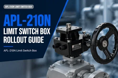
The APL-210N is engineered for durability and ease of use in demanding industrial environments. Its standout features include:
- Robust housing options: Choose glass-reinforced plastic for lightweight corrosion resistance or aluminum alloy for higher impact strength. Both meet IP67 (NEMA 6) protection.
- Flexible switch options: 1 or 2 SPDT switches with silver or gold contacts. Customizable for dry contact (NO/NC) configurations. Rated for 5A/250VAC or 10A/125VAC.
- Quick-set cams: Adjustable with a standard screwdriver; locking screws prevent movement after calibration.
- High-visibility indicator: Shatter-resistant polycarbonate dome with red/green halves—visible from 10+ meters, even in bright light.
- Terminal block: Screw-type terminals accept 14 AWG wire; optional pre-wired cable glands for rapid installation.
These features make the APL-210N suitable for indoor and outdoor use, from clean assembly floors to wet, dusty environments like wastewater treatment plants.
How to Select and Implement the APL-210N Limit Switch Box Correctly
Proper selection and installation ensure long-term reliability. Follow this structured approach:
Step 1: Verify Valve Gearbox Mounting Interface
Check the mounting pattern (ISO 5211 F05/F07 or custom) and shaft dimensions. The APL-210N bracket accommodates square or double-D shafts up to 14 mm. Confirm the gearbox has a tapped hole for the bracket screw. If not, use the supplied adapter kit. Also verify that the gearbox output torque rating is compatible with the valve's operating torque requirements—consult the Valve Gearbox datasheet for details.
Step 2: Mount and Wire the APL-210N
Secure the bracket to the gearbox using provided bolts. Attach the switch box body and connect wiring per your control schematic. Use cable glands rated for the environment (PG9 or NPT 1/2). Ensure wires are properly terminated and strain-relieved. For outdoor installations, apply dielectric grease to contacts to prevent corrosion.
Step 3: Calibrate Cam Settings for Accurate Feedback
Manually cycle the valve to fully open and closed positions. Loosen the cam locking screw, rotate the cam until the switch clicks (use a multimeter for continuity), then tighten. Repeat for the second cam if using two switches. Test operation both locally and from the control room. Document the cam positions for future reference.
After installation, perform a full stroke test and verify that the indicator dome aligns with the actual valve position. The APL-210N requires no regular maintenance beyond periodic inspection of seals and wiring—typically every 12 months or as dictated by the plant's preventive maintenance schedule.
FAQ
What is the typical lifespan of the APL-210N Limit Switch Box?
Under normal conditions (clean, moderate temperature, non-corrosive atmosphere), mechanical switches are rated for over 1 million cycles. The housing and indicator dome can last 10+ years indoors; outdoor installations may require seal checks every 2 years.
Can the APL-210N be used in hazardous (explosion-proof) locations?
The standard APL-210N is not intrinsically safe or explosion-proof. For hazardous areas, consider an explosion-proof enclosure variant specifically certified for Class I/II Div. 1 or 2. Always consult a safety engineer for proper selection.
Does the APL-210N require an external power supply?
No. The switch contacts are passive dry contacts (NO/NC). They simply open or close an externally powered circuit (e.g., 24VDC PLC input, 120VAC indicator lamp). No internal power is needed.
How do I adjust the cam for a 90-degree quarter-turn valve?
Rotate the valve fully open. Loosen the cam for the open signal, rotate it until the switch clicks, then tighten. Repeat for closed position. Use a multimeter to confirm continuity at each limit. Typical cam adjustment range is 0-90° with 5° graduations for fine tuning.
What output signals can the APL-210N provide?
The standard APL-210N provides dry contact (NO/NC) signals. For analog feedback (e.g., 4-20mA or 0-10V), a potentiometer or transmitter module can be added via an accessory module (sold separately). This enables continuous position measurement rather than just end-of-travel indication.
Can the APL-210N be retrofitted to existing valve gearboxes?
Yes, provided the gearbox has a standard mounting pattern (ISO 5211) and accessible shaft. The bracket and cam design accommodate most quarter-turn actuators. For non-standard interfaces, an adapter kit may be required. Always measure shaft height and diameter before ordering.
Conclusion
The APL-210N Limit Switch Box is a practical, cost-effective solution for adding reliable position feedback to Valve Gearbox systems. By understanding its components, selection criteria, and proper installation procedures, engineering and procurement teams can ensure a smooth rollout and improve operational visibility. For further exploration of compatible Valve Gearbox solutions and automation accessories, browse the full range of precision control components.