
Pneumatic Actuator Selection Guide for Industrial Valves
Most pneumatic actuator selection errors trace back to the same root cause: the actuator is chosen by valve size or by catalogue page rather than by the torque the valve actually demands under operating conditions. A DN300 butterfly valve and a DN300 ball valve can present very different break-to-open torque profiles, and an actuator that performs well on one may stall on the other — or fail to return the valve to its safe position when air is lost.
This guide provides a structured selection path for quarter-turn pneumatic actuators used on industrial valves. It covers the eight inputs that determine the correct configuration, the mechanical differences between rack-and-pinion and scotch-yoke designs, the fail-safe decision between single-acting and double-acting, mounting interface verification, torque sizing against air supply pressure, and the maintenance factors that influence long-term reliability. The Pneumatic Actuator range referenced throughout spans both rack-and-pinion and scotch-yoke configurations, with model-specific torque documentation available for verification.
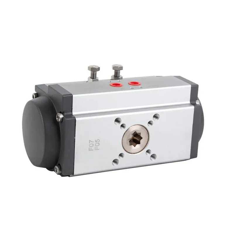
How to Select a Pneumatic Actuator — Eight Inputs That Determine the Configuration
Before comparing models, compile these eight data points. Each one eliminates a class of unsuitable configurations and prevents the quotation-comparison problem where two suppliers propose different actuator sizes because they worked from different assumptions.
| # | Selection Input | What to Confirm | Why It Decides the Configuration |
|---|---|---|---|
| 1 | Valve type | Ball, butterfly, plug, or other quarter-turn valve | Determines the required rotation angle (typically 90°) and the torque profile |
| 2 | Required torque | Break-to-open, running, end-to-close, maximum allowable stem torque | Sizes the actuator output against the worst-case demand, not average running torque |
| 3 | Double acting or single acting | Fail-close, fail-open, or no fail-safe requirement | Determines whether spring cartridges are needed and changes the effective output torque |
| 4 | Air supply pressure | Minimum available pressure at the actuator inlet, not compressor nameplate pressure | Actuator output torque drops as supply pressure drops; sizing must use the minimum |
| 5 | Operating temperature | Ambient and media temperature range | Affects seal material, lubricant, and whether low-temperature options are required |
| 6 | Mounting standard | ISO 5211 flange size, stem dimensions, drive type | Confirms mechanical compatibility with the valve; prevents installation rework |
| 7 | Corrosion and explosion-proof requirements | Indoor, outdoor, washdown, corrosive atmosphere, hazardous area classification | Drives housing coating, sealing class, and whether ATEX/IECEx documentation applies |
| 8 | Feedback and accessory requirements | Limit switch box, solenoid valve, positioner, air filter regulator | Determines the NAMUR interface configuration and control signal path |
A selection that omits input 2 (torque) or input 4 (minimum air pressure) is not a selection — it is an estimate. Input 3 (fail-safe mode) is often decided late in the project, but it changes the actuator size because a spring-return unit must overcome both valve torque and spring force during the return stroke. Input 6 (mounting) is the most common source of installation delay when it is deferred to the order stage.
Rack and Pinion vs Scotch Yoke — Two Torque Delivery Mechanisms
Both designs convert linear piston motion into rotary output, but they do so through different mechanical arrangements, and that difference determines which valve services each design suits.
A rack-and-pinion actuator uses a piston with a linear gear rack that meshes with a pinion on the output shaft. As the piston moves, the rack drives the pinion through a fixed arc. The torque output is relatively uniform across the stroke, the housing is compact, and the modular design accepts spring cartridges, limit switch boxes, and solenoid valves through standard interfaces.
A scotch-yoke actuator uses a piston connected to a slotted yoke that converts linear motion into rotary motion through a sliding block. The torque output is not uniform: it peaks near the mid-stroke and drops toward the ends. This torque profile is advantageous for high-torque valve operation where the breakaway demand occurs early in the stroke and the valve requires less torque once moving, but it requires careful sizing against the valve’s actual torque curve rather than a single nominal figure.
| Parameter | Rack and Pinion | Scotch Yoke |
|---|---|---|
| Typical application | Quarter-turn valves in standard isolation and on/off service | High-torque valve operation, large valves, severe service |
| Torque characteristics | Relatively uniform across stroke | Peaked at mid-stroke; lower at stroke ends |
| Structure | Compact, modular, standard accessory interfaces | Heavy-duty housing, high output torque capacity |
| Maintenance | Relatively straightforward seal and guide replacement | Designed for harsh conditions; verify wear-component access |
| JIMAI configuration | Quarter-turn rack-and-pinion range | HXY Series Scotch Yoke Pneumatic Actuator |
The rack-and-pinion configuration is the default for most butterfly and ball valve applications where the torque requirement falls within its range and the valve does not demand the higher output capacity of a scotch-yoke design. The quarter-turn rack and pinion range covers this standard service pattern with a symmetrical rack-and-pinion structure intended for smooth operation and a hard-anodized cylinder for wear resistance.
The scotch-yoke configuration becomes relevant when the valve torque demand exceeds what a rack-and-pinion unit can deliver at the available air pressure, or when the application involves large valves where the torque peak aligns with the scotch-yoke output curve. The HXY Series Scotch Yoke configuration uses an X-ring seal arrangement and a copper sliding mechanism, with air connections configured at the front and a lifting lug on top for installation handling.
The selection question is not which design is “better” in general, but which torque curve matches the valve’s demand at the minimum available air pressure. A rack-and-pinion unit sized correctly will outperform a scotch-yoke unit sized on a nominal torque figure that does not account for the valve’s actual breakaway profile.
Single Acting vs Double Acting — The Fail-Safe Decision
The choice between single-acting (spring-return) and double-acting operation is a process-safety decision before it is a mechanical one.
A double-acting actuator requires air pressure to move the valve in both directions. If air supply is lost, the valve remains in its last position. This is acceptable for isolation valves that do not require a defined safe state on air failure, and it is often preferred where the valve is expected to hold position during a utility interruption.
A single-acting actuator uses air pressure to move the valve in one direction and stored spring energy to return it in the other. The spring cartridges are arranged to produce either fail-close or fail-open action, and the number of springs determines the return torque. A single-acting actuator does not simply “add a spring” to a double-acting unit: the spring force opposes the air force during the power stroke, so the effective output torque in the power direction is lower than the same housing in double-acting configuration, and the spring torque in the return direction must be verified against the valve torque at the fail-safe position.
The practical sizing consequence is that a single-acting actuator is often one frame size larger than a double-acting unit for the same valve, because the spring quantity must be sufficient to return the valve against its seating or unseating torque without air assistance. Selecting a single-acting actuator by matching the double-acting torque rating alone will produce a unit that fails to return the valve.
| Operating Mode | Air Failure Behavior | Torque Consideration | Typical Use |
|---|---|---|---|
| Double acting | Holds last position | Output torque in both directions determined by air pressure | Isolation valves without defined fail-safe requirement |
| Single acting, fail-close | Springs drive valve closed | Spring torque must exceed valve torque at close position; power-stroke torque reduced by spring force | Safety shutdown valves, process isolation requiring closure on air loss |
| Single acting, fail-open | Springs drive valve open | Spring torque must exceed valve opening torque; power-stroke torque reduced by spring force | Cooling water valves, vent valves requiring open position on air loss |
A related configuration question arises when the valve must be operated manually during air failure in addition to the spring-return action. In that case, a declutchable gearbox mounted between the actuator and the valve provides a lever-operated manual override. The declutchable gearbox range is configured for this sandwich-mount arrangement, and the selection depends on the actuator output interface and the valve mounting flange rather than on the actuator alone.
The accessory set also changes with the operating mode. A double-acting actuator controlled by a solenoid valve requires a 5/2-way valve; a single-acting actuator requires a 3/2-way valve with spring-return exhaust. Limit switch boxes for position feedback and positioners for modulating control interface through the NAMUR pattern on the actuator body. The actuator accessory range covers these interface components, and the selection should be confirmed against the actuator model rather than assumed from the accessory catalogue alone.
Mounting Standards — ISO 5211, NAMUR, and the Interface Verification Step
A pneumatic actuator with the correct torque rating but the wrong mounting interface cannot be installed on the valve. Three interface standards govern most industrial installations, and each applies to a different connection point.
ISO 5211 specifies the flange dimensions, driving component dimensions, and reference torque values for the interface between a part-turn valve and its actuator or gearbox. The standard defines a family of flange sizes (F10, F12, F16, and others), and the actuator must be ordered with the matching flange pattern and drive configuration. An actuator described as “ISO 5211 compliant” without the specific flange code is not a verified match. The current edition of the standard, ISO 5211:2026, is listed in the ISO catalogue and available for preview through standards distributors.
NAMUR (the NAMUR recommendation NE 14 and related interface standards) governs the mounting pattern for solenoid valves and positioners on the actuator body, as well as the namur interface for air connections. A NAMUR-compatible actuator accepts a NAMUR-direct solenoid valve without additional tubing or adaptation. The NAMUR organization publishes its recommendations and interface standards through its official standards channel.
VDI/VDE 3845 specifies the mounting interface for accessories such as limit switch boxes and positioners on quarter-turn actuators, including the bracket dimensions and shaft coupling. An actuator without the VDI/VDE 3845 interface pattern may require a custom bracket for accessory mounting.
| Standard | Interface Point | What It Confirms |
|---|---|---|
| ISO 5211 | Valve-to-actuator flange and drive | Flange size, bolt pattern, stem/drive dimensions, reference torque |
| NAMUR | Actuator-to-solenoid/positioner | Air port pattern, mounting hole spacing, control signal path |
| VDI/VDE 3845 | Actuator-to-accessory bracket | Bracket dimensions, shaft coupling, position feedback mounting |
The verification step is straightforward but frequently skipped: obtain the valve top-flange drawing and stem dimensions, confirm the ISO 5211 flange code and drive type, then confirm that the proposed actuator carries the matching flange and drive. For accessories, confirm the NAMUR and VDI/VDE 3845 patterns on the specific actuator model rather than on the series description. A separate guide on mounting interface standards for pneumatic actuators covers the dimensional checks in more detail; until that guide is published, the FAQ section addresses common interface questions.
Sizing by Torque and Air Supply — The Table That Prevents Under-Sizing
Actuator output torque is not a single number. It depends on the air supply pressure at the actuator inlet, the operating mode (double acting or spring return), and — for spring-return units — the number of springs installed. A sizing table that lists one torque figure per model without stating the pressure and spring condition is not sufficient for selection.
The governing relationship is:
Actuator output torque at minimum air pressure ≥ Valve torque × Safety factor
For double-acting actuators, the output torque in each direction is determined by the air pressure acting on the piston area. For spring-return actuators, the power-stroke torque is the air torque minus the spring torque, and the return-stroke torque is the spring torque alone. Both values must be compared against the valve torque at the relevant position.
| Condition | Parameter to Confirm | Selection Consequence |
|---|---|---|
| 5 bar air supply | Nominal output torque at 5 bar | Use the minimum site pressure, not the compressor setpoint |
| 6 bar air supply | Maximum output torque at 6 bar | Do not size at 6 bar if the site cannot guarantee 6 bar at the actuator inlet |
| Low-temperature service | Seal and lubricant compatibility | Standard seals may harden; confirm low-temperature option |
| High-cycle operation | Life-cycle rating and wear components | Verify cycle rating for the specific model; confirm seal replacement interval |
| Hazardous area | ATEX / IECEx / SIL documentation for exact model | Certificate scope varies by model; confirm revision |
The safety factor question deserves explicit treatment. A common approach is to apply 1.25 to 1.5 times the valve break-to-open torque, but the appropriate factor depends on the service: clean, frequently operated valves may use the lower end, while dirty, high-temperature, or infrequently operated valves may require a higher factor. The safety factor should be stated in the selection record, not left as an implicit assumption.
The torque data required for this comparison comes from the valve manufacturer: break-to-open, running, and end-to-close torque for quarter-turn valves, plus the maximum allowable stem torque. If the valve torque is unavailable, it can be estimated from valve type, size, pressure class, and seat material, but the estimate should be confirmed before order placement.
Product Matching — Configurations for Specific Valve and Service Requirements
The actuator family is the starting point; the configuration is what matches the specific installation. The following configurations address requirements that a standard rack-and-pinion or scotch-yoke unit does not cover on its own.
Three-position control. Some valve applications require an intermediate position in addition to fully open and fully closed — for example, a 0°–45°–90° sequence for partial flow or purge positioning. The 0°–45°–90° three-position rotary configuration provides this intermediate stop through a dual-piston arrangement, and the selection requires confirming the intermediate position angle, the torque at each position, and the control valve sequence.

Local position indication. A valve equipped with an actuator but without a position indicator leaves the operator guessing whether the valve is open, closed, or partially open. The rotary actuator with scale indicator adds a visible degree scale to the actuator top, allowing local position confirmation without a separate limit switch box. This is a low-cost addition that is often omitted from the initial specification and added later at higher cost.
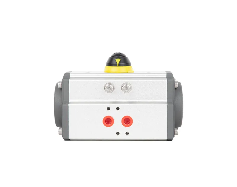
Condensation control on chilled-water valves. A butterfly valve in a chilled-water or HVAC application can form condensation on the actuator and valve body when the cold surface meets humid ambient air. The anti-condensation butterfly valve configuration uses a long heat-insulating neck to separate the cold valve body from the actuator and prevent surface condensation and dripping. This is a service-specific configuration, not a general-purpose actuator option, and it should be specified when the application involves chilled water below ambient dew point.
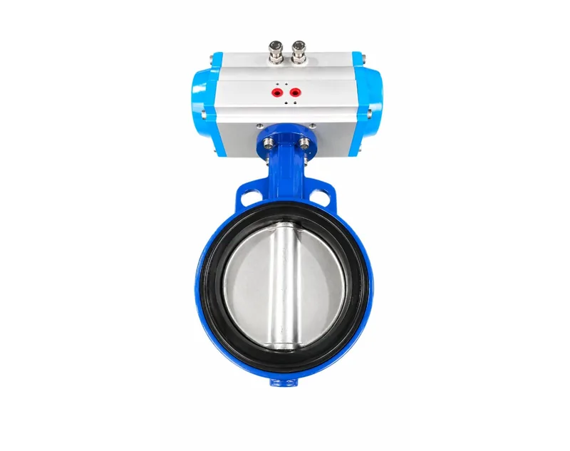
High-torque severe service. When the valve torque demand exceeds the rack-and-pinion range at the available air pressure, the scotch-yoke configuration becomes the relevant family. The HXY Series is configured for this service pattern, and the selection should verify the torque curve at the actual stroke position where the valve demand peaks, not only the nominal maximum torque.
For applications where the actuator is combined with a manual gearbox — for example, a large butterfly valve that requires both automated operation and a manual override — the actuator and gearbox are selected as an assembly. The valve gearbox range provides the quarter-turn gearbox side of this combination, and the interface between actuator output and gearbox input must be confirmed against the ISO 5211 pattern on both components.
Practical Application Scenarios
Scenario A — Chemical dosing isolation valve.
A DN80 ball valve in a chemical dosing line requires 180 N·m break-to-open torque. The line operates at 5 bar air supply. The valve must close on air failure to prevent upstream chemical migration. The area is classified as ATEX Zone 2.
The selection inputs are: quarter-turn ball valve, 180 N·m break torque with 1.5 safety factor = 270 N·m required output, single-acting fail-close, 5 bar minimum air supply, ATEX documentation for the exact model, ISO 5211 F07 flange. The actuator must be sized so that the spring torque at the fail-close position exceeds the valve seating torque, and the power-stroke torque at 5 bar exceeds 270 N·m. A double-acting unit would not provide the fail-close action, and a rack-and-pinion unit sized on the double-acting torque rating would be undersized for spring-return service.
The ATEX documentation requirement is model-specific. The certificate scope must be confirmed for the exact actuator size and configuration, not assumed from the series listing. The chemical industry application overview provides context on the environmental and documentation requirements that apply to this sector.

Scenario B — Power plant cooling water butterfly valve.
A DN600 butterfly valve requires 2,400 N·m break-to-open torque at 6 bar air supply. The valve is in a cooling water header and must open on air failure to maintain flow. The installation is outdoors but not classified as hazardous.
The selection inputs are: quarter-turn butterfly valve, 2,400 N·m break torque with 1.3 safety factor = 3,120 N·m required, single-acting fail-open, 6 bar supply, IP67 enclosure for outdoor service, ISO 5211 F14 flange. The actuator size must provide spring torque sufficient to open the valve against the seating load, and the power-stroke torque at 6 bar must exceed 3,120 N·m. If the spring-return rack-and-pinion range cannot deliver this combination within the available envelope, the scotch-yoke family becomes the relevant alternative — but the torque curve must be checked at the open position, not only at mid-stroke.
The power generation application overview covers the typical valve services and environmental conditions for this sector, including the distinction between indoor and outdoor enclosure requirements.

Maintenance Factors That Affect Selection — pneumatic actuator maintenance
Actuator selection does not end at commissioning. The maintenance profile of the selected design influences total cost of ownership, and some maintenance considerations should be built into the selection decision rather than addressed after installation.
Air quality. The most common cause of premature actuator wear is contaminated or wet air supply. Particulate matter and moisture accelerate seal wear and corrosion inside the cylinder. A filter-regulator on the air supply is a low-cost addition that extends seal life; the selection should confirm whether the actuator is specified with an air filter regulator or whether the site provides clean, dry air at the required dew point.
Seal and lubricant compatibility. Standard nitrile seals are suitable for general service, but low-temperature or high-temperature applications may require different elastomers. The operating temperature range in the selection inputs determines whether standard seals are adequate. Lubricant selection follows the same logic: standard grease may not be suitable for low-temperature service, and the maintenance interval depends on the lubricant grade and operating conditions.
Cycle frequency and wear components. A valve that cycles once per day has a different wear profile from one that cycles every few minutes. The actuator life-cycle rating should be compared against the expected cycle count, and the wear components — seals, guide rings, and shaft bearings — should be accessible for replacement. For high-cycle service, confirming the availability of seal kits and the replacement procedure before order placement avoids a situation where a failed seal requires actuator replacement rather than repair.
Manual override accessibility. If the actuator is mounted in a location where the manual override cannot be reached, the override provides no value during a failure. The selection should confirm that the override location and the required operating force are compatible with the installation. For buried or elevated valves, a remote override or a declutchable gearbox may be required.
The specific maintenance interval and seal replacement procedure should be confirmed for the selected model, and the service support section provides the after-sales and spare-parts support path.
FAQ
How do I choose a pneumatic actuator size?
Start with the valve manufacturer’s break-to-open torque, apply the project safety factor, and compare the result against the actuator output torque at the minimum site air pressure. For spring-return actuators, verify both the power-stroke torque and the spring-return torque against the valve torque at the relevant position. Do not size on nominal valve size or on running torque alone.
What is the difference between single acting and double acting?
A double-acting actuator requires air pressure in both directions and holds its last position on air failure. A single-acting actuator uses air in one direction and spring force in the other, providing a defined fail-close or fail-open position when air is lost. The spring-return unit is typically one frame size larger for the same valve because the spring force reduces the available power-stroke torque.
Which is better, rack and pinion or scotch yoke?
Neither is universally better. Rack-and-pinion actuators provide relatively uniform torque across the stroke and a compact modular design suitable for most quarter-turn valve applications. Scotch-yoke actuators provide a peaked torque curve suitable for high-torque and large-valve service. The correct choice depends on the valve’s torque demand at the minimum air pressure and the stroke position where that demand occurs.
What air pressure is required?
The required air pressure is the minimum pressure at the actuator inlet that produces sufficient output torque for the valve with the safety factor applied. This is not the compressor nameplate pressure. A system that supplies 6 bar at the compressor may deliver 4.5 bar at the actuator after line losses, and the actuator must be sized at the lower figure.
How do I match an actuator to a butterfly valve?
Confirm the valve’s ISO 5211 flange code, stem dimensions, and break-to-open torque. Select a quarter-turn actuator with the matching flange and drive, and verify output torque at the minimum air pressure against the valve torque with safety factor. If the valve is in chilled-water service, consider the anti-condensation configuration to prevent condensation on the actuator.
What is ISO 5211 mounting?
ISO 5211 is the international standard that defines the flange dimensions, driving component dimensions, and reference torque values for the interface between a part-turn valve and its actuator or gearbox. The standard uses flange size codes such as F07, F10, and F12, and the actuator must be ordered with the matching flange pattern and drive configuration.
How can I extend pneumatic actuator service life?
Provide clean, dry air through a filter-regulator, confirm seal and lubricant compatibility with the operating temperature, and match the actuator life-cycle rating to the expected cycle count. For high-cycle service, confirm the availability of seal kits and the replacement procedure before order placement.
What accessories are typically required?
A solenoid valve for on/off control, a limit switch box for position feedback, and an air filter regulator for air quality. A positioner is added for modulating control. The accessory interface should be confirmed against the NAMUR and VDI/VDE 3845 patterns on the specific actuator model.
CTA
-
Request Actuator Sizing — Provide valve type, torque data, air supply pressure, and fail-safe requirement for a model recommendation with torque verification. Contact JIMAI
-
Send Valve Torque Data — Submit valve manufacturer torque values for comparison against actuator output at the minimum site pressure.
-
Download Actuator Catalogue — Torque tables, dimensional drawings, and accessory interface details. Visit download section
-
Request 3D CAD — STEP/STP and 2D files for space verification and system integration.
-
Compare JAT and HXY Series — Rack-and-pinion vs scotch-yoke torque characteristics and application boundaries. View Pneumatic Actuator
This article is part of JIMAI’s technical content library. No direct sales or pricing information is included. All technical discussions aim to help you make informed purchasing decisions.