APL-210N Limit Switch Box for Valve Position Feedback

2026.07.20

Article Overview: This article explains the function, components, and integration of the APL-210N Limit Switch Box in valve automation systems. It covers how this device provides reliable position feedback, its key features, and how it works with a Valve Gearbox to improve process control. The content is intended for technical buyers and engineers evaluating limit switch box options for industrial applications.

What Is an APL-210N Limit Switch Box?

A limit switch box is an electromechanical device mounted on a valve actuator to indicate the valve’s open or closed position. The APL-210N Limit Switch Box is a compact unit that includes a visual position indicator, a quick-set cam mechanism, a terminal strip for wiring, and an easy-to-mount bracket. It converts the rotary motion of the actuator shaft into electrical signals that can be sent to a control system, PLC, or indicator panel. This feedback is essential for remote monitoring, safety interlocks, and automated sequencing in industrial processes such as chemical processing, water treatment, and oil and gas.

The APL-210N is designed for non-hazardous environments, while its explosion-proof counterpart, the ITS-300, serves hazardous locations. Typical applications include quarter-turn valves (ball, butterfly, plug) coupled with pneumatic or electric actuators.

Why Choose the APL-210N Limit Switch Box for Valve Automation?

APL-210N Limit Switch Box illustration

Selecting a limit switch box involves balancing cost, reliability, and ease of installation. The APL-210N Limit Switch Box offers several practical advantages for plant engineers and procurement teams:

  • Quick-set cams – The cam mechanism can be adjusted without removing the cover, reducing setup time during commissioning or maintenance.
  • Visual position indicator – A clearly visible dome or flag shows valve status locally, helping operators verify position at a glance.
  • Terminal strip – The pre-wired terminal block simplifies electrical connections and troubleshooting.
  • Compact footprint – The low-profile design fits easily on most valve actuators without interfering with other components.
  • Durable construction – The housing is made of corrosion-resistant materials suitable for industrial environments.

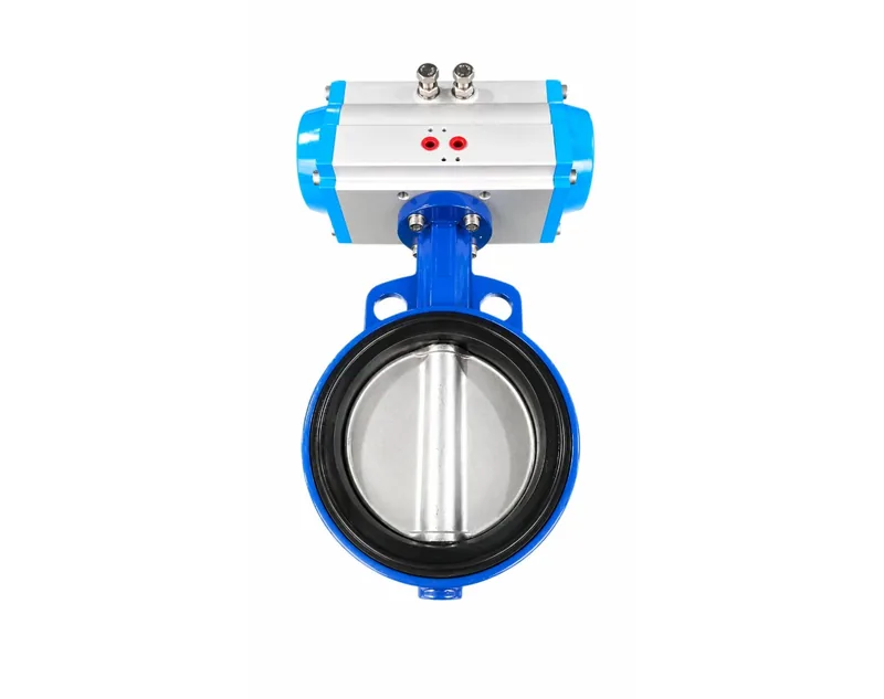
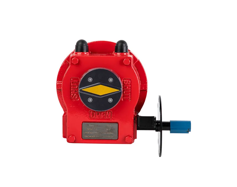
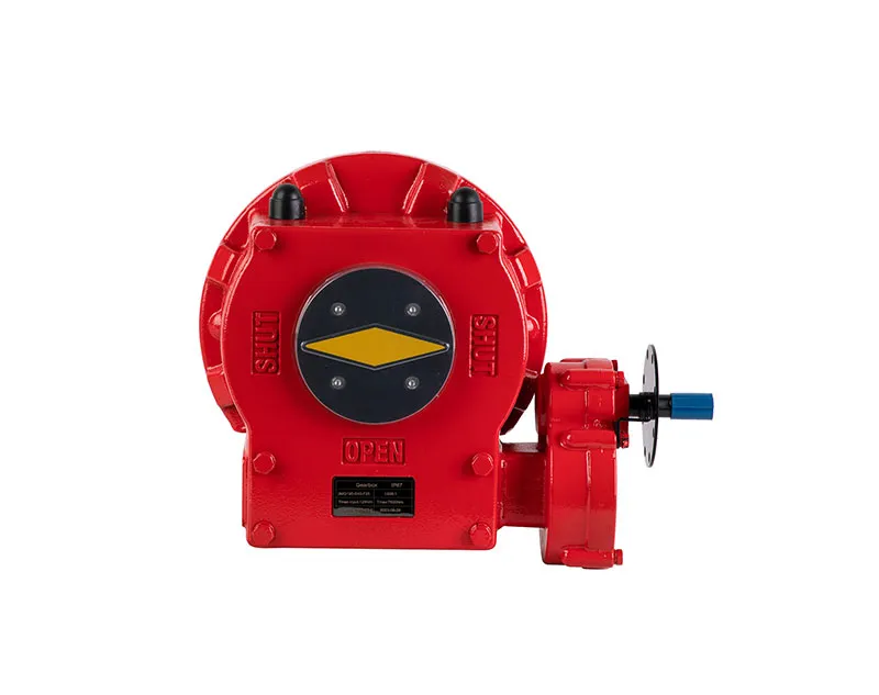
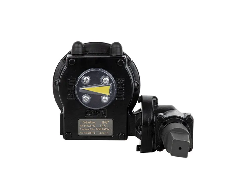
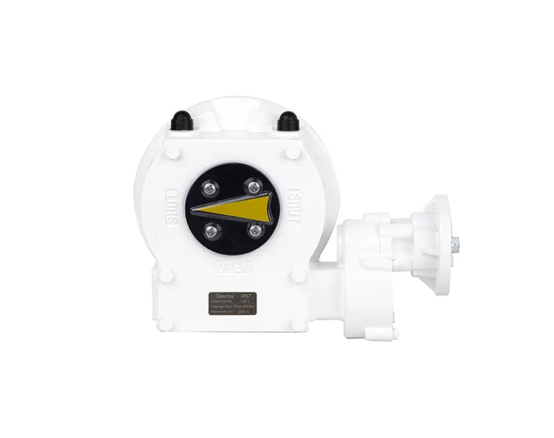
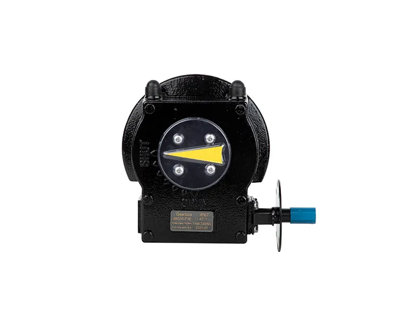
These features contribute to lower total cost of ownership by reducing installation labor and minimizing unscheduled downtime. For applications requiring integration with a manual override or gear reduction, the APL-210N pairs effectively with a Valve Gearbox to ensure accurate position feedback even when the valve is operated manually.

How Does the APL-210N Limit Switch Box Integrate with a Valve Gearbox?

A Valve Gearbox is often used to provide manual operation capability or to increase torque for large valves. When combined with a limit switch box, the gearbox must still transmit the rotary position to the switch mechanism. The APL-210N Limit Switch Box is designed to mount directly onto the actuator’s top drive, which is typically a 14mm or 22mm square shaft, matching common gearbox output shafts. Integration is straightforward:

Step 1: Mount the Bracket

Attach the provided bracket to the actuator or gearbox mounting pad using the supplied screws. Ensure the bracket is aligned with the drive shaft center.

Step 2: Connect the Shaft Coupler

Slide the limit switch box’s shaft coupler onto the actuator or gearbox shaft. Tighten the set screws to prevent slippage while allowing free rotation.

Step 3: Set the Cams

Rotate the valve to the fully open position and adjust the open cam until the switch actuates. Repeat for the closed position. The quick-set design eliminates the need for tools.

Step 4: Wire the Terminal Strip

Connect the switch wires to the terminal strip according to your control system wiring diagram. The terminal block is clearly labeled for common configurations.

Step 5: Test Operation

Cycle the valve through its full stroke and verify that the position indicator and electrical signals match the valve status. Adjust cam positions if needed.

This integration ensures that position feedback remains accurate whether the valve is actuated pneumatically or manually via the gearbox. The APL-210N’s robust construction withstands the vibration and mechanical loads common in valve actuation.

What Are the Key Selection Criteria for Limit Switch Boxes?

When evaluating limit switch boxes for your application, consider the following factors to ensure compatibility and long-term reliability:

Phase 1: Assess Environment and Safety Ratings

Determine whether the installation is in a general-purpose area or a hazardous location. For explosive atmospheres, choose an explosion-proof model such as the ITS-300. For standard industrial settings, the APL-210N is a cost-effective choice.

Phase 2: Verify Mechanical Compatibility

Check shaft size, coupling type, and mounting dimensions. The APL-210N accepts square shafts from 11mm to 22mm, making it compatible with most actuators and gearboxes.

Phase 3: Evaluate Electrical Requirements

Confirm voltage, current ratings, and switch configuration (SPDT/DPDT). The APL-210N typically supports 5A at 250VAC, suitable for PLC inputs and indicator lights.

Phase 4: Confirm Environmental Protection

Ensure the ingress protection (IP) rating matches the exposure. The APL-210N offers IP67, resistant to dust and temporary water submersion.

Phase 5: Plan for Maintenance Access

Choose models with tool-free cam adjustment and easily accessible terminal strips to simplify future servicing.

Additional selection checkpoints:

  • Cable entry size and quantity – Typical models include two PG13.5 or NPT ½” entries.
  • Temperature range – Standard operating range is -20°C to +80°C; special versions available for extreme conditions.
  • Visual indicator type – Dome or flag indicators provide local feedback; some models offer LED options.
  • Switch life expectancy – Mechanical switches typically rated for 1 million cycles; proximity sensors last longer in high-cycle applications.

Frequently Asked Questions

What is the difference between the APL-210N and the ITS-300 limit switch boxes?

The APL-210N is a standard limit switch box for non-hazardous locations, while the ITS-300 is certified explosion-proof for use in environments with flammable gases (Exd IICT6). The ITS-300 also features stainless steel screws and reinforced housing for added durability.

Can the APL-210N Limit Switch Box be used with a Valve Gearbox?

Yes. The APL-210N mounts directly on top of most valve gearboxes that have a standard square shaft output. Proper alignment and secure coupling ensure accurate position feedback during both automatic and manual operation.

How do I adjust the cams on the APL-210N?

Remove the cover to access the cam assembly. Rotate the valve to the desired endpoint and turn the corresponding cam until you hear or feel the switch actuate. Tighten the cam lock screw. No tools are required for the quick-set cam design.

What electrical ratings does the APL-210N support?

Typical ratings include 5A at 250VAC (resistive) and 0.5A at 125VDC. Confirm with the manufacturer for specific inductive load applications to avoid contact welding.

Is the APL-210N suitable for outdoor installation?

Yes, with an IP67 enclosure rating, it withstands rain, dust, and hose-down. However, direct exposure to corrosive chemicals may require additional protection or the use of an explosion-proof model like the ITS-300.

Conclusion

The APL-210N Limit Switch Box provides a reliable, cost-effective solution for valve position feedback in automated systems. Its key features—quick-set cams, visual indicator, terminal strip, and compact design—simplify installation and reduce maintenance. When integrated with a Valve Gearbox, it ensures accurate feedback even during manual operation. For engineering managers and buyers evaluating options, the APL-210N offers a balanced combination of performance and value for general-purpose industrial environments. For hazardous areas, the ITS-300 explosion-proof variant is the recommended choice. Always consider your specific application requirements, including environmental conditions and mechanical compatibility, to select the most appropriate limit switch box for your process.

Talk to Our Expert

CHAT NOW
Talk to Our Expert.
Captcha Code
GET IN TOUCH NOW
img

Quick Help: Contact one of our experts and we'll get back to you in 24 hours!

We value your privacy
We use cookies to provide you with a better online experience, analyse and measure website usage, and assist in our marketing efforts.
Accept All